Documentation
PROCESS OF FABRICATION AND ASSEMBLY
Preface
'Handcraft was once the tool of commodity, but today
it is the machine that is the tool of commodity.
Therefore, architecture produced as an industrial
product would naturally become a new vernacular.'
by Stephen Kieran and James Timberlake
(extracted from 'The Hand and The Machine' Chapter of Refrabricating Architecture:
How Manufacturing Methodologies Are Poised To Transform Building Construction)
Traditionally architecture physical models were hand-made to express the ideas, concepts, materials, lighting, space, human activity and scale in three dimensional form. Nowadays, high technology has been introduced to create complicated design models, making a shift from hand-made to factory-made models. Before fabricating 3 precedent models, UNSW BENV7813 Course students are introduced by the workshop staffs with the available tools and facilities (Metal Shaping, Laser Cutting, 3D Printing, Timber Turning, CNC Milling, Casting Room) in Squarehouse to assist and improve their model-making skills. This marks the starting point to plan the modelling techniques and imagine the physical model's appearance produced by the high technology machines from the research materials. Each precedent model's construction process is documented in 3 parts: Planning Process, Manufacturing Process and Assembly Process.
1. Nakagin Capsule Tower (Designed by Kisho Kurokawa in Tokyo, Japan b. 1972)
a) Planning Process (3 days)
By analysing the floor plan and section drawings, a focus area has been highlighted to present the precedent's concept and construction idea that is relevant to my design studio's research question focusing on 'How can modular construction provide flexible and affordable housing strategies for the changing needs of home owners?'.

:: Selected area of focus from the plan and section drawings
Based on the digital floor plan and axonometric drawing, you can clearly understand how the capsule units connect to the building with the bolting and interlocking system attaching to the steel columns that is assumbly situated hidden inside the concrete shear wall that is connected to the concrete spiral stairs and central concrete lift core. Initially I planned to use only 3D printing technique to contruct this model by using PLA clear and white filament to show the transparency and hidden construction components in the building. However, I was advised by the workshop staff that the outcome produced from the PLA clear filament is translucent and hard to see through. Therefore, I changed the modelling technique for those elements to laser cutting 2mm thick acrylic clear and laminated them to show the transparency and solidness of the structure. The model was planned to show the constuction assembly of the building, rather than in 1:100 to show the entire building's appearance or 1:20 to show the interior space of the capsule unit. Therefore, scale 1: 50 is the most appropriate size to present the engineering concept.
 |
| :: Sketches of connection assembly and modelling technique used |
b) Manufacturing Process (1.5 weeks)
Firstly, digital model was built from scratch by analysing the floor plan and section drawings using Rhino software. The capsule units, podium floor slabs and I-beams were saved in stl file and later imported to Cura software to print in Ultimaker 3 and S5 using PLA white filament. 2% infill density with fast 0.2mm printing setting and supports were set up as well as making sure that thickness of the elements were not lesser than 2mm before sending to print. From here, 3D printing technique shows a similar method of fabrication that reflects on the process of prefabrication of the capsule units in the real world.
 |
| :: Exploded axonometric diagram to be presented in physical model |
 |
| :: Small elements were printed using the smaller 3D printer Ultimaker 3 |
 |
| :: Longer and larger elements were printed using the 3D printer Ultimaker S5 |

:: The spiral stairs were broken into 5 levels to minimize the printing duration and cost
 |
| :: 3D printing capsule units under progress |
Concrete shear wall (laminated 4 layers 2mm acrylic clear), central lift core (2mm acrylic clear), podium's pilotis (laminated 2 layers 6mm acrylic clear) and base box (3mm basswood) were saved according to the layer settings in the laser cutter template in Rhino fileThe lineworks were arranged according to the material size (800x400mm) sold in Squarehouse before bringing the file to print in Trotec Laser Cutter Software. It is safe not to leave lesser than 0.7mm gap or else the material will bend as the laser hits and produces heat on the material surface.
 |
| :: Sample of laser cutting template of the lift core and shear wall saved in Rhino file |
c) Assembly Process (3 days)
The first element to be assembled was the base with dovetail joint and later the podium's legs can slot into the holes before attaching to the podium's floor slabs. The shear walls were glued to the I-beams whereas the spiral stairs were glued and stacked to surround the central lift core; not gluing onto the base to present the model in an exploded 3D form. Besides, it is easy to disassemble which reflects on the flexibility idea of the project.
 |
| :: Gluing the I-beam to the shear wall before attaching the capsule unit to the structure |

:: Assembly process of physical model


 |
| :: Final outcomes of Nakagin Capsule Tower model |
2. Long Museum West Bund (Designed by Atelier Deshaus in Shanghai, China b. 2014)
a) Planning Process (3 days)
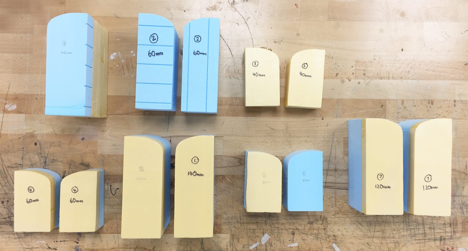
I try to challenge myself using a completely new technique to construct this model which is casting method. Firstly, I drew out the mould shape and initially planned to use laser cutting elements to stack them together to create the appropriate thickness of the cast. However, there will be layers and grains surfaced on the cast which are not I personally prefer to show. Therefore, I decided to make the moulds using foam and cut them using the foam cutter machine in Squarehouse. This method can will be cost efficient, reuseable and easy to make. I did not try using sand or timber or plastic moulds because I personally think these methods may be time-consuming and not reuseable.
 | ||
| :: Initial sketches and dimensions of the mould and cast
Based on the digital drawings I found in the references, I highlighted the focus area and analysed its structural system and orientation of 'vault-umbrella' structures and constructed a digital 3D model using Sketchup, making sure that they were drawn in the correct dimensions in a scale of 1:100 to show 4 levels of the building. From here, we can explore the lighting and spatial experience inside the space through single or double height volumes and dark or bright spaces in this exhibition building.
|

 |
| :: Plan drawings of Long Museum West Bund |
Before cutting the foam, 2 pieces of laser cut curved mould templates were cut using laser cut machine, along with the base box and floor slabs. The laser cut curved mould templates were used to sandwich the foam with masking tape. These templates can be reused many times and through this method, it can form a nice cut curved outline and save time and material instead of eyeballing or drawing the outline on the foam during the foam-cutting process. The mould was meant to cast a 10mm thick structure with a 20mm high for first trial.
 |
| :: Sandwiched foam cut left with clean curved edge |
 |
| :: First attempt of casting small T-structure |
 |
| :: Destroyed moulds and cast were left with unclean curved surfaces |
After cutting the curved moulds, I tried the first attempt of casting the small T structure by finishing up the mould box and taped it around with masking tape and sealed it with plastine at the edge corners to prevent any leakage. Before making the casting mixture, water was poured into the mould box to test its waterproofing standard. If there was a leakage, more tapes are secured at the edges and holes. When it was tested again with water and successfully left with no water leakage, we started making the casting mixture using water and Barnes hydrostone in a ratio of 3:1 based on the preferred volume needed to cast. Black oxide powder was poured into the water to make the dye. While making the mixture, water and black oxide were poured into the bucket before inserting the hydrostone powder into the bucket. This method can minimise the amount of bubbles hidden inside the mixture. Spatula was later used to stir the mixture consistently and poured into the mould. The cast was left to set and dry for an hour. While removing the mould, it was easy to get rid of the vertical wall surfaces but not the curved mould. The reason was I did not apply vaseline or layer a transparent sheet on the surface which in the end, I had to destroy the curved mould with a scalpel to remove the cast. Despite this, I was very satisfied with the outcome and decided to make more moulds with different heights and sizes. All casts were made with a thickness of 10mm.
 |
| :: Laser cut template for curved mould template, base box and base box
Double sided tape was used to stack the curved foam together in order to cast it at the assigned thickness as planned in the sketchbook. This time, transparent sheet was sticked onto the curved surface to provide a smooth curve glossy finish as well as for ease removal purposes.
|


 |
| :: Seven moulds were made using the foam cutter and stacked according to the assigned thickness |
The process of casting can be viewed from this link, Making casting mixture
 |
| :: A vibrator tool was used to remove any bubbles hidden in the cast |
Based on the different forms, the hardest to cast was the L-shaped structure, second hardest was the big T-structure and the easiest was the small T-structure. While making the L-shaped cast, I had failed 3 times due to excess leakage at the corners and also the thick layer of cast. Here's a tip, before pouring the cast into the mould, prepare a box of tissues for emergency cleaning.
 |
| :: Excessive leakage from the L-shaped mould, what a waste of material! |
 |
| :: Easy removal of curved mould as well as providing a clean curved cast surface |
The final touch of casting is cleaning the cast with sandpaper and water. Cleaning it in the sink would remove the impurities easily in a clean way. The below image is the before and after cleaning the cast with wet sandpaper. The cast turns darker after cleaning with water and set to dry. Soon, it will becomes lighter again after drying but not as light as before cleaning with wet sandpaper.


The facade box was cut with 3mm frosted acrylic sheet with basement layer engraved and light scoring on the mullions. Besides, 5mm diameter holes were cut in several areas so we can take a sneak peek of the interior space of the model when it was covered with the translucent facade box. This not only casts soft lighting into the space but also reflect the light on the floor slabs, providing atmospheric space for exhibition in the play of light and shadows.
 |
| :: Laser cut Rhino template for making the facade box |
 |
| :: Engraving the material takes the longest duration to complete the laser cutting job |
c) Assembly Process (2 days)
The casted T-structures were first slotted into the holes on the base according to the floor plan sketched in my sketchbook. Human figures were later placed to show the scale of the model and basement floor slabs were inserted to the structures and finally the facade box was used to cover the model.
 |
| :: Process of assembly for Long Museum West Bund model |
 |
| :: Close-up detail view of the model |
 |
| :: Interior views from seeing through the holes on the facade box |
My first casting experience was fun yet challenging. Without the assistance and advices from the workshop staffs and friends, I would not be able to produce these complicated structure at first place.
3. Redfern Suburb Urban Design Analysis
a) Planning Process (1 day)
My main concept of this model is to present the Redfern suburb analysis as my design studio's project site is located at 600-638 Elizabeth Street, Redfern NSW 2016. While extracting the information from the Redfern map in AutoCAD, I can clearly understand the formal and street arrangement of the suburb based on the building programs allocated in the cadastral map from the past. This residential suburb was develoiped from the past history of industrialization and opening of Redfern Railway Station that attracted many new residents to move into the suburb to stay closer to workplace. More future developments were planned to construct in this suburb. Therefore, this model is built in a scale of 1:5000 to analyse the surroundings of the suburb in a larger context.
 |
| :: Redfern Suburb Map Box diagram |
From here, different trays featuring the railway lines, public space and streets were cut using laser cutter with 1.5mm jarrah board and 2mm clear to show the overlaying layers of information of mapping in three-dimensional form. The digital drawings were produced in Rhino file as well as the laser cutting template for the trays.


Below image is the sketch planning for the timber track for the trays using 6.5mm thick balsa wood. 3mm grooves were cut using the table saw with the assitance from the wood workshop staff for the 1.5mm jarrah board and 2mm acrylic clear sheet trays to slide through.
 |
| :: Sketch diagram for making the sliding tray |
b) Manufacturing Process (2 days)
After preparing the laser cut files in Rhino template, the trays and tray box were cut using the laser cutter machine with 1.5mm jarrah board and 2mm acrylic clear sheet. Engraving takes the most time to process which therefore my top layer map surface took approximately 64 minutes to complete due to the engraving frame. The purpose I engraved the frame is to make the surface look translucent and hide the ugly internal layer of the sliding track.
 |
| :: Laser cutting the street tray |
 |
| :: Some bits left broken due to the thin gaps lesser than 0.7mm |
Dimensions were marked on the 6.5mm balsa wood and sent to the wood workshop for groove slicing with the assistance from the staff. Clamp handles were used to cut the inner layer of the wood and slowly slide it through.

c) Assembly Process (1 day)
The map box was first to assemble and covered with top map layer and bottom 6mm acrylic black matt. 1.5mm jarrah board were laser cut with dovetail joint to conceal the 6.5mm sliding track balsa wood. Later the sliding trays were inserted into the map box. A final touch is gluing the site plan onto the top map layer.


 |
| :: Corner joint detail |
 |
| :: Final touch on process of assembly
This sliding concept that I tried to imply into the model that also reflects on my design studio's project's sliding draw concept.
|
Final Remarks
 |
| :: Set up a mini photography studio with clean background and soft lighting |
Choosing a good perspective angle and taking photos under a soft lighting, not fully exposed background are crucial to produce good quality images as well as saving time in photo-editing the models. Photographing these models would take me 5 hours to complete the process. I personally prefer taking photos in the morning with soft natural lighting cast onto the models, instead of afternoon with bright sunlight.
Throughout this course, I was able to plan and produce good quality models with the introduction of workshop facilities and assistance from the tutors and workshop staffs. Machine-produced models have taken over the quality of hand-made models in my case as well as saving time but not cost.
T H A N K Y O U


Comments
Post a Comment